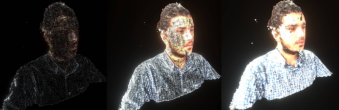
Point cloud rendering with Unity
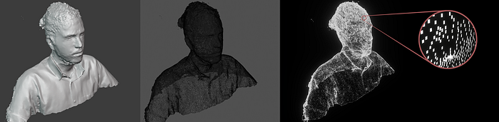
In summary, Point Clouds are a series of points in space that are presented visually instead of an interconnected topology. You may have seen this visualization in Photogrammetry scanning. In that scenario, with the help of a depth sensor or Photogrammetry software, we can generate many points out of photos and then combine them and make a mesh out of it.
But here, we have a different purpose. Our goal is to get vertices properties from a mesh and then represent a Point Cloud out of that.
As you can guess, PointClouds has so much potential, but my reason for starting this journey was the Aesthetic side of point clouds. Some Point Clouds artists inspired me, and I took up the challenge to do it myself.
While the original method in this article provides a hands-on approach to rendering meshes as point clouds, Unity’s VFX Graph now offers a more efficient way to achieve similar results by sampling particles on mesh surfaces. This updated method simplifies the process, offering greater flexibility and performance.
Here we explore the traditional approach for learning purposes, but encourage readers to explore VFX Graph for modern solutions.
Shaders
You should have an overall knowledge of Shaders and GPU for the first step. One of the best resources for starting is TheBookOfShaders.com. Here’s a summary so we can move on to the following parts.
Shaders are a set of orders that run on every pixel (or vertex). The GPU does this job, but why? Imagine we have a screen with a 2880x1800 aspect, and if our program runs 60 frames per second, our Shader must run 311040000 times per second! CPUs cannot handle this amount of process easily. Let’s look at the structure of CPU and GPU.
In simple words, the CPU is like an extra powerful process pipe that can handle oversized packages one by one. On the other side, the GPU is more like millions of smaller pipes that each one can process lighter problems but works simultaneously.

So we saw GPU could help us enormously, but it has some drawbacks. Threads need to be blind and memoryless to work parallel. Blinds mean that a specific thread doesn’t know what others’ threads do, and by being memoryless, it has no memory of what it was doing in the past. These handicaps make Shader unpopular among new developers.
Usually, we have some public variables that every thread can access, like mouse position and resolution. Also, we have some private variable that’s different in every thread. For example, in the below GLSL code, we make a gradient canvas using pixels’ positions.
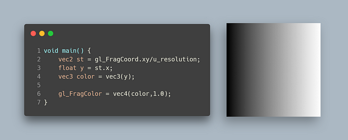
In the above, by dividing the position of every pixel by the resolution, positions are normalized between 0 and 1. The left bottom of the canvas position is (0,0), and the top-right pixel is (1,1). As you see, the x position is passed to a color vector and makes this gradient canvas out of it.
This concept is good to continue our journey, but if you want to dive into Shaders, check out TheBookOfShaders.com.
Here are some of my Shader practices with GLSL:
Fishes in noisy water on ShaderToy.
Star Rider shader on ShaderToy.
Composition II with Red Blue and Yellow” from Piet Mondriaan
Summary of steps
- Storing vertices data in buffers. We can get vertices data in any form we prefer, but I got them directly from the mesh.
- With APIs that Unity gave us, draw procedural geometry as the same number as vertices count.
- In the vertex shader, we use the vertex position (also UV and normals for other adjustments) to place each point correctly.
- Use a computer shader to make VFX for points(optional).
Create Point Cloud out of mesh data
First of all, we need a buffer to store our vertices’ positions. We should declare the buffer length and size of each data in bytes. As every vertex position consists of 3 floats (4 Byte data each), we set 12 Byte in the size parameter.
positionsBuffer = new ComputeBuffer(vertices.Lenght,3*4);
positionsBuffer.SetData(vertices)
We don’t need any special implementation in our Compute Shader in the current step as we want to pass data and show them without any effect.
Now it’s time to use Unity graphic API to draw instance meshes. Here a default quad mesh is passed to instantiate as our points; also a material, bound, and the number of instances. For more information about DrawMeshInstancedProcedural , you can check Unity documentation.
//_Positions is our buffer
float3 position = _Positions[unity_InstanceID];
As I mentioned, this method draws the same mesh multiple times using GPU instancing. It means that they are in the same position and don’t have any extra components to adjust. Thus we must adjust them using a vertex shader.
In this project, Unity’s Shader Graph is used. To access buffers in Shader Graphs, you need some extra nodes that you can find in my PointCloud repository; also, you can find all the implementations and a deeper understanding in this article.
To access buffers and pass the desired data, we need to add a Custom Function node and write some HLSL code in it.
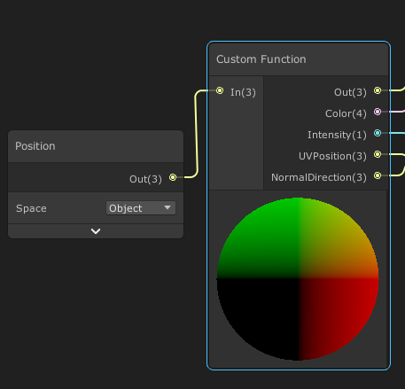
At the beginning of the .hlsl file, I declared our buffers and variables that I wanted to pass. We can set some if conditions to announce this part specifically compiled for procedural drawing.
As you can see, I have also stated other buffers and variables. We will use them later. Here we want to set the position, rotation, and scale of each point, so we need _positions (local position of vertexes that we stored), _objectRotation(rotation of entire points), _step (scale of each point), and _scale (scale of entire points).
Implement transformation matrix for points
Now, if we run the project, all the Quads (the same number as our mesh vertices) are located in the center of the world and face the Z-axis(as we use default unity’s quad for our points).
For that, we need to use the ConfigureProceduralmethod in .hlsl file. This indicates that the surface shader must invoke a ConfigureProcedural function for each vertex. Now we can retrieve our data from buffers with the identifier of the instance currently being drawn.
Here we have access to each vertex data from the buffers we passed to the material. We need to declare a transformation matrix and multiply it with the point matrix to set them in their correct position. We can replace our desire matrix with unity_ObjectToWorldand unity uses it to convert vertices from object space to world space, so it will multiply automatically.
Here is a cheat sheet from the matrices I used in the project. As transformation matrices are 4x4, we need to add another row and column to rotation matrices.
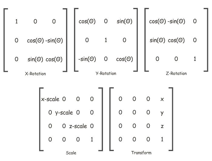
Simply, I defined all matrices that I’ll need:
Here is the tricky part. We should multiply out matrices in a specific order.
- First, I declared
rotationMatrixby multiplying all other three matrices based on the axes.
2. second, I set our points to their world position(position of analogous vertex * scale of all points) + whole point cloud world position with worldPos matrix.
3. Then, I transferred the point to its local origin by localPosNegative matrix.
4. After that, I rotated the coordinates using rotationMatrix.
5. Then, I transformed them back into their local position and applied each point's scale.
_scalein worldPos matrix is referred to the whole object scale, but the_stepin scale matrix is the scale of each point.
At this point, we can generate our Point Cloud, and we can move and rotate all of them. The problem is that all the points(quad meshes) are faced toward their local Z axis.
As it has always suggested, it’s better to use quaternion rotation rather than simple Euler angles x,y,z. Hence it’s better to convert
transform.rotationwhich is a quaternion to a transformation matrix usingMatrix4x4.TRS()and use this as a rotation applier in the material. In this case, there is no need for the above rotation calculations, and this matrix can be used straightly.
For this issue, I used a simple trick. I have made a node(LookAtDirection) in the Shader graph that gets a position and a direction vector. The return of this Node is also a position that goes into the Vertex Position of the Vertex Shader.
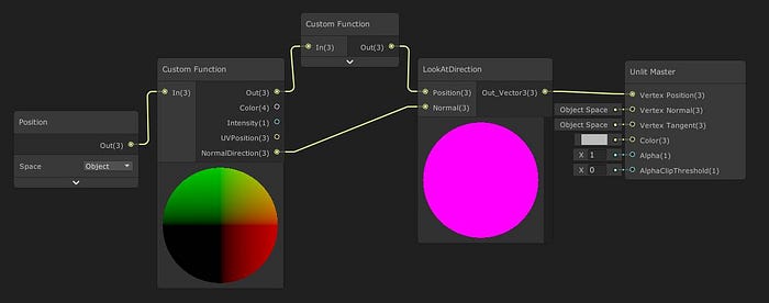
LookAtDirection nodeMost of the time, we prefer our points direction to be the same as its Normal direction. We can send any data and buffer to the material like the position buffer. For Normals, we have:
private void SetNormalsData(){normals = sourceMesh.normals;normalsBuffer = new ComputeBuffer(normals.Length, 3 * 4);normalsBuffer.SetData(normals);material.SetBuffer("_Normals", normalsBuffer);}
In the LookAtDirection node, I used the RotateAroundAxis function. It allows us to rotate each specific point along a direction.
This is a visual representation of finding the axis and amount of rotation.
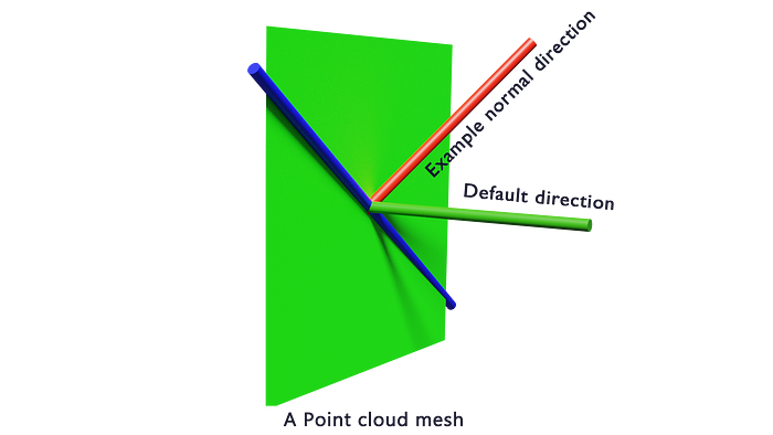
In the above, there is a visual representation of one single point. At default, it was facing toward the green vector(0,0,-1). The red direction is our goal(normal). We want to rotate the plane to make green and red vectors in the same direction. We must rotate the plane along the blue direction. We can do a Cross product on red and green vectors and normalize it to find the blue vector. And finally, to find the angle between red and green vectors, we can use the Dot product.
Dot product : a · b = |a| × |b| × cos(θ)
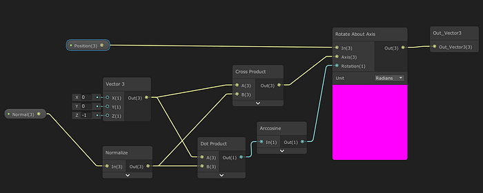
RotateAroundAxis nodeFurthermore, we can set camera direction instead of normals; hence, we’ll have a billboard effect.
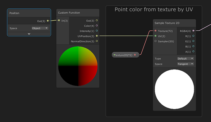
Color and Texture
For getting color from a specific texture, we need the UV position of each point(vertex). I made a buffer of UV vectors and set them on the material like before. In Shader, we can simply use UV position in Sample Texture 2D node and get the color.
Physics simulation
One of the best advantages of using Point Clouds is that we can control every single point separately. Here Compute Shaders come in handy. One of the most fantastic effects is physics simulation that I got inspired by IRCC-Mesh Deformation.
Like in Shader, we must declare buffers and vectors that we need in Compute Shader. The main method is CSMain. Also, we need to specify the dimension and size of the GPU threads that we want to use. To make it straight, here, I used one dimension.
We need some extra data from an object to simulate it in Compute Shader, and the most straightforward shape for calculating is a sphere.
Also, I used _drag to slow down the velocity over time. _positionsbuffer contains points positions as we saw it before. Also, we have a new _velocity buffer that is zero at the beginning.
Inside CSMain we can get data from buffers based on the id. each thread has its position in id and as we declare one dimension, we can access each point instance number by using id.x.
In line 11, I new velocity calculated based on ball radius and distance of the ball and that point position. If you are not familiar with smoothstep operation take a look at TheBookOfShaders-SmoothStep.
Also, to execute Compute Shader, it’s essential to Dispatch it in Unity Update function.
protected void DispachComputeShader(){
//We declared gruops of 64 threads in Compute Shader, so we must Divide total points by 64int groups = Mathf.CeilToInt(vertices.Length / 64f);computeShader.Dispatch(0, groups, 1, 1);}
As you consider, we can apply various effects, and the only limitation is our imagination. I believe Point Clouds has many potentials, and they’ve not been used sufficiently in the media like video games. I hope this article was helpful for you.
And finally, Special thanks to Dr. Yaghmaee and Shahriar Shahrabi for their great help.
Here is my point cloud repository that all the codes are available. https://github.com/ahmaderfani12/PointClouds
Faani, the game that I made with Point Clouds. https://jashgames.itch.io/faani
Easy Point Cloud Unity Package. https://assetstore.unity.com/packages/slug/201205

